
How to Choose a Gas Spring: A Practical Sizing Guide (Imperial & Metric)
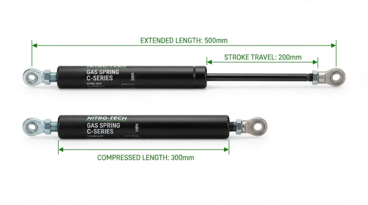
Gas spring sizing is the process of matching four mechanical parameters to your hinged door, lid, or articulated arm: extended length (100 to 1,000 mm), stroke travel (10 to 500 mm), extension force rating F1 (50 to 2,500 N or 11.2 to 562 lbf), and rod-to-cylinder diameter series (such as 8/18 mm or 10/22 mm).
The single biggest sizing mistake is matching gas spring force directly to the dead weight of the panel. Always calculate rotational torque around the hinge pivot using your centre of gravity and bracket lever arm, then leave 5 to 10 mm of reserve stroke so the piston never bottoms out.
Bring effortless, precision motion to your next build by sizing your gas spring to exact stroke lengths (10 to 500 mm), calibrated extension forces (50 to 2,500 N), and verified rod diameters (6 to 14 mm) across elastic locking, rigid locking, or non-locking lift configurations.
- Specification Range: Stroke travel from 10 to 500 mm (0.39 to 19.69 in.), force ratings from 50 to 2,500 N (11.2 to 562 lbf), and rod diameters from 6 to 14 mm.
- Locking Options: Non-locking lift support struts, elastic lockable gas springs, and rigid locking gas struts in compression or extension locking directions.
- OEM Production Support: Custom valve damping, 304 and 316 stainless steel options, modular end fittings, and rapid prototype turnaround for North American and global OEMs.
Key Takeaways for Gas Spring Sizing
- Size Torque, Not Dead Weight: A 250 N (56 lbf) lid rarely uses a 250 N gas spring. Hinge leverage dictates the required F1 force rating.
- Protect the Piston With Reserve Stroke: Leave 5 to 10 mm (0.20 to 0.40 in.) of uncompressed travel when the door is closed so the strut never acts as a hard mechanical stop.
- Convert Newtons and Pounds Accurately: Divide Newtons by 4.448 to get pounds-force (100 N ≈ 22.48 lbf), or multiply pounds-force by 4.448 to specify in Newtons.
- Account for the K-Factor Rise: Force increases by 10% to 60% as the rod enters the cylinder. Check compressed force (F2) so operators can close the panel without straining.
- Mount Rod-Down Whenever Possible: Orienting the piston rod downward keeps internal damping oil against the main gland seal for consistent lubrication and smooth end-of-stroke braking.
Why Precision Gas Spring Sizing Makes or Breaks Your Build
Every engineer and maintenance supervisor knows the feeling when motion control goes wrong. If you specify a gas strut that is even 15% underpowered, a 45 kg (100 lb) steel access canopy turns into a sudden slam hazard the first time winter temperatures drop on a jobsite. Go 20% too strong, or miss your compressed length by 8 mm, and you watch a brand-new sheet-metal prototype warp its hinges, shear a ball stud, or fight the operator every time they try to latch it shut.
On the other hand, when your gas spring sizing is dialled in, the hardware disappears into the experience. A heavy medical diagnostic arm floats effortlessly at the touch of two fingers. An industrial CNC enclosure glides open to 90° and decelerates to a whisper-quiet hydraulic stop. At Newton, we believe motion control should never be a guessing game of trial-and-error swaps.
Whether you call them gas springs, gas struts, lift supports, or hydro-pneumatic cylinders, this practical sizing guide connects every step of the specification process. We have structured this page around five core engineering steps, each paired with a quick-reference data table and a direct link to our specialised deep-dive guides.
Measure & Envelope
Confirm extended length (Lext), compressed length (Lcomp), and usable stroke (10 to 500 mm) with a 5 to 10 mm safety reserve.
Force Rating (F1)
Calculate moment equilibrium around the hinge pivot to specify extension force from 50 to 2,500 N (11.2 to 562 lbf).
Series & Progression
Select rod and tube diameter (6/15 mm up to 14/28 mm) and tune K-factor force progression (1.15 to 1.60).
Locking & Fittings
Choose non-locking, elastic locking, or rigid locking valves, then match ball sockets, eyelets, or clevis forks.
How Does Gas Spring Sizing Differ Across OEM Industries?
A gas strut sized for a subterranean utility vault faces completely different duty demands than a locking actuator on an ICU surgical table. Before crunching numbers, benchmark your project against the six primary OEM sectors Newton supports:
| Industry Sector | Typical Mechanism | Preferred Motion Type | Common Series & Force | Critical Engineering Requirement |
|---|---|---|---|---|
| Automotive & Specialty Vehicles | Service body doors, tonneau covers, bonnet hoods, ambulance cabinets | Non-Locking Lift | 8/18 mm or 10/22 mm (150 to 900 N) | Cold-weather thermal compensation (-30°C to +80°C) and 10 mm ball socket articulation |
| Furniture & Ergonomics | Executive chair tilt, sit-stand desks, luxury recliner backrests | Elastic Lock | 8/18 mm or 10/28 mm (100 to 600 N) | Smooth release pin actuation, low K-factor for easy manual reset, silent damping |
| Medical Devices | Surgical tables, patient stretchers, diagnostic imaging arms, overbed tables | Rigid Lock | 10/22 mm or 10/28 mm (150 to 1,250 N) | Zero deflection under load, 304/316 stainless wipe-down resistance, precision cable release |
| Industrial Equipment | CNC safety guards, compressor enclosures, packaging machine access hoods | Non-Locking Lift | 10/22 mm or 14/28 mm (300 to 2,500 N) | High buckling margin, clevis or eyelet shear strength, oil and coolant seal durability |
| Aerospace | Pilot and crew seating, overhead stowage bins, ground support access panels | Rigid Lock | 6/15 mm or 8/18 mm (50 to 650 N) | High strength-to-weight ratio, strict cycle-life traceability, vibration stability |
| Rail Transit | Driver console adjustment, passenger reclining seats, exterior battery bay doors | Elastic Lock | 8/18 mm or 10/22 mm (120 to 1,000 N) | Heavy-duty cycle endurance, tamper-resistant clevis hardware, consistent end damping |
Step 1: How Do You Measure Existing Gas Struts for Replacement or Benchmarking?
To measure a gas strut accurately, dismount it from the bracket to remove load compression, then measure Extended Length (Lext) from the centre of one end fitting to the centre of the opposite end fitting, followed by Stroke (S), Rod Diameter (d), and Cylinder Diameter (D).
When replacing an existing lift support or reverse-engineering a competitor benchmark, never trust measurements taken while the strut is still bolted inside a closed or half-open cabinet. Even a partially worn gas spring holds high internal pressure, and measuring thread-to-thread instead of centre-to-centre can throw off your opening angle by 10° to 15°.
| Dimension Parameter | Symbol | Exact Measurement Reference Points | Required Tool | Common Pitfall to Avoid |
|---|---|---|---|---|
| Extended Length | Lext | Centre of rod end fitting hole/ball to centre of tube end fitting hole/ball (fully open) | Steel tape or rule (mm / in.) | Measuring only the black cylinder barrel or excluding the end fittings |
| Stroke Length | S | Exposed silver/black piston rod length from the cylinder wiper seal to the rod thread shoulder | Steel rule or caliper | Including the threaded rod stud or fitting neck inside the stroke number |
| Compressed Length | Lcomp | Extended length minus usable stroke (Lext – S), measured centre-to-centre | Calculated (Lext – S) | Trying to compress a high-force strut by hand on the shop floor |
| Rod & Tube Diameter | d / D | Outer diameter of the moving piston rod (d) and outer diameter of the cylinder body (D) | Digital vernier caliper | Guessing diameter with a tape measure (6 mm vs 8 mm rods look similar at a glance) |
| Extension Force | F1 | Stamped Newton rating on cylinder label (e.g., 450N) or calibrated load-cell compression test | Part label or force gauge | Assuming a dead strut’s current resistance reflects its original factory charge |
Need to measure an unmarked or failed gas strut on the bench? Follow our complete step-by-step measurement guide covering thread-to-thread vs. centre-to-centre standards and bench force testing.
Read Guide: How to Measure Gas StrutsStep 2: How Do You Calculate Gas Spring Force (F1) for a New Build?
Calculate required extension force (F1) by multiplying the door’s total weight (W) by the horizontal distance to its centre of gravity (Lcg), dividing by the gas spring’s perpendicular lever arm (d) and the number of struts (n), and multiplying by a 1.15 safety factor.
In North America, specification sheets often mix metric Newtons (N) and imperial pounds-force (lbf). Before running torque math, unify your units using these exact conversion factors:
1 lbf = 4.44822 N | 1 N = 0.22481 lbf | Weight in Newtons (W) = Mass (kg) × 9.81 m/s²
Because a hinged lid acts as a rotational lever, mounting your gas spring close to the hinge pivot gives the strut a short lever arm (d). The shorter that lever arm, the more force the gas spring must exert to hold the weight aloft:
F1 = [ (W × Lcg) ÷ (d × n) ] × 1.15
| Application Example | Panel Mass & Weight (W) | Centre of Gravity (Lcg) | Strut Lever Arm (d) | Qty (n) | Calculated Force (F1 per Strut) | Recommended Newton Series |
|---|---|---|---|---|---|---|
| Medical Monitor Hood | 6.0 kg (59 N / 13.2 lbf) | 180 mm (7.1 in.) | 90 mm (3.5 in.) | 2 | 70 N (15.7 lbf) | 6/15 mm Series |
| Truck Utility Toolbox Lid | 18.0 kg (177 N / 39.7 lbf) | 300 mm (11.8 in.) | 120 mm (4.7 in.) | 2 | 255 N (57.3 lbf) | 8/18 mm Series |
| CNC Machine Safety Guard | 36.0 kg (353 N / 79.4 lbf) | 420 mm (16.5 in.) | 140 mm (5.5 in.) | 2 | 610 N (137.1 lbf) | 10/22 mm Series |
| Heavy Commercial Canopy | 85.0 kg (834 N / 187.5 lbf) | 550 mm (21.7 in.) | 165 mm (6.5 in.) | 2 | 1,600 N (359.7 lbf) | 14/28 mm Series |
Want to calculate exact bracket coordinates and opening hand forces? Dive into our full engineering tutorial with worked formulas for horizontal, vertical, and angled lids.
Read Guide: Gas Spring Force Calculation
Step 3: How Do You Use a Gas Strut Size Chart to Match Dimensions and Series?
Once you know your target stroke and F1 force rating, use a gas strut size chart to pair your rod and cylinder diameter series (6/15 mm, 8/18 mm, 10/22 mm, or 14/28 mm) with standard extended and compressed lengths.
Every gas spring requires internal dead length to house its piston, guide bushing, high-pressure gland seal, and damping oil. In addition, when you compress a long piston rod under high thrust, the rod behaves like a structural column subject to Euler buckling. Stepping up to a larger rod-to-cylinder diameter series prevents the rod from bowing or binding mid-stroke.
| Diameter Series (Rod / Tube) | Standard Stroke (S) | Compressed Length (Lcomp) | Extended Length (Lext) | Force Range F1 (N) | Force Range F1 (lbf) | End Thread |
|---|---|---|---|---|---|---|
| 6 / 15 mm Compact | 50 to 150 mm (2.0 to 5.9 in.) | 115 to 215 mm (4.5 to 8.5 in.) | 165 to 365 mm (6.5 to 14.4 in.) | 50 to 400 N | 11.2 to 90 lbf | M6 × 1.0 |
| 8 / 18 mm Standard | 80 to 250 mm (3.1 to 9.8 in.) | 155 to 325 mm (6.1 to 12.8 in.) | 235 to 575 mm (9.3 to 22.6 in.) | 80 to 750 N | 18.0 to 169 lbf | M8 × 1.25 |
| 10 / 22 mm Heavy Duty | 100 to 350 mm (3.9 to 13.8 in.) | 185 to 435 mm (7.3 to 17.1 in.) | 285 to 785 mm (11.2 to 30.9 in.) | 100 to 1,250 N | 22.5 to 281 lbf | M8 or M10 |
| 14 / 28 mm Extra Heavy | 150 to 500 mm (5.9 to 19.7 in.) | 245 to 595 mm (9.6 to 23.4 in.) | 395 to 1,095 mm (15.6 to 43.1 in.) | 250 to 2,500 N | 56.2 to 562 lbf | M10 × 1.5 |
Mandatory Design Check: The 5 to 10 mm Stroke Reserve Rule
When comparing your closed bracket-to-bracket distance against a size chart’s Compressed Length (Lcomp), always verify that your closed mounting distance equals at least Lcomp + 5 to 10 mm (0.20 to 0.40 in.). This reserve stroke ensures the mechanical door stop absorbs the closing load rather than the internal gas spring piston.
Looking for the complete stroke-by-stroke lookup table in both millimetres and inches? Browse our master dimension chart covering 10 to 500 mm strokes across all rod series.
View Full Gas Strut Size Chart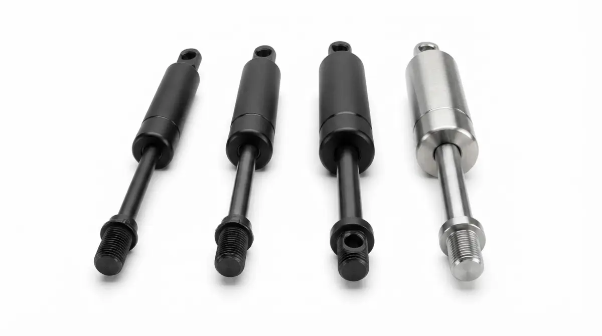
Step 4: Are Gas Springs Constant Force? Understanding K-Factor Progression
No, gas springs are not constant-force devices. As the solid steel piston rod plunges into the sealed cylinder during compression, the rod’s volume reduces the internal space available for the nitrogen gas, causing pressure and output force to rise by 10% to 60%.
This progressive force increase is called the K-Factor (force ratio), defined as the fully compressed extension force (F2) divided by the fully extended force (F1). In addition, when an operator manually pushes a door closed, they must overcome both the compressed gas force (F2) and internal seal sliding friction (FR):
K = F2 ÷ F1 | F2 (Compressed Extension Force) = F1 × K | F4 (Peak Closing Effort) = F2 + FR
| Diameter Series | Rod-to-Tube Area Ratio | Typical K-Factor Range | Extended Force (F1) | Compressed Force (F2 = F1 × K) | Ergonomic Impact on User Feel |
|---|---|---|---|---|---|
| 6 / 15 mm (Low K) | ~16% volume displacement | 1.18 to 1.25 | 400 N (90 lbf) | 472 to 500 N (106 to 112 lbf) | Flat force curve; very smooth, consistent effort to push closed |
| 8 / 18 mm (Medium K) | ~20% volume displacement | 1.25 to 1.32 | 400 N (90 lbf) | 500 to 528 N (112 to 119 lbf) | Balanced progression; suits general automotive and furniture panels |
| 10 / 22 mm (Standard Heavy) | ~21% volume displacement | 1.28 to 1.38 | 400 N (90 lbf) | 512 to 552 N (115 to 124 lbf) | Strong initial breakaway push when unlatching heavy horizontal lids |
| 10 / 18 mm or Oil-Filled (High K) | ~31%+ volume displacement | 1.45 to 1.60 | 400 N (90 lbf) | 580 to 640 N (130 to 144 lbf) | Steep force rise; provides maximum bottom-end lift but requires high closing force |
Curious how F1, F2, F3, and F4 appear on a gas spring force-displacement diagram? Read our engineering deep dive on tuning K-factors and internal damping oil volume.
Read Guide: Are Gas Springs Constant Force?Step 5: How Do You Select the Right Gas Spring End Fittings?
Select gas spring end fittings that match your bracket mounting style while isolating the piston rod from lateral side-loading. Most industrial struts feature modular metric threads (M6, M8, or M10) on the rod tip and cylinder cap so you can configure ball sockets, eyelets, clevis forks, or lockable actuator heads.
| End Fitting Type | Angular Freedom | Common Thread Sizes | Typical Fitting Adder Length | Primary Engineering Advantage |
|---|---|---|---|---|
| 10 mm & 13 mm Ball Socket | ±15° to 18° multi-axis swivel | M6, M8, M10 | 18 to 25 mm per end | Eliminates lateral side-loads and rod bending when wide sheet-metal doors flex |
| Eyelet (Flat Blade) | Single-plane pivot around pin | M6, M8, M10 | 15 to 22 mm per end | Slim profile and high shear capacity for precision clevis-pin brackets |
| Clevis Fork (U-Yoke) | Single-plane rigid straddle | M6, M8, M10 | 20 to 30 mm per end | Maximum mechanical security; prevents pop-off on heavy machinery guards and transit doors |
| Lockable Release Head | Direct lever or Bowden cable | M8 × 1.0, M10 × 1.0 | 22 to 35 mm (rod end) | Translates push-button, paddle, or remote cable travel into internal valve actuation |
Need exact thread pitch dimensions, ball stud diameters, and bracket mounting orientations? Explore our complete hardware specification guide.
Read Guide: Gas Spring End Fittings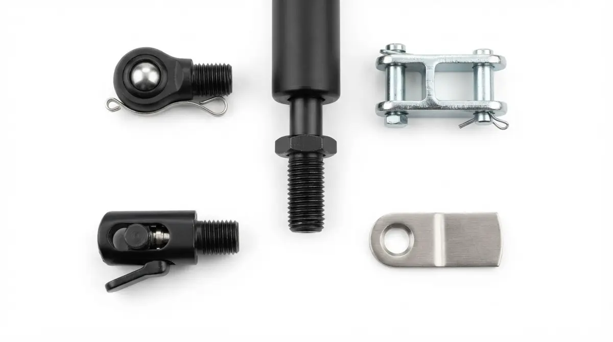
When Should You Specify Lockable Gas Springs vs. Non-Locking Lift Struts?
Specify a non-locking lift support strut when a door only needs to travel between fully closed and fully open stops, and specify a lockable gas spring when the user must arrest and hold the load at variable intermediate positions along the stroke.
Newton manufactures three distinct hydro-pneumatic architectures so you can tailor locking stiffness to your application:
- Non-Locking Lift Support Struts: Continuous counterbalance thrust from 50 to 2,500 N. Nitrogen gas and damping oil flow through a calibrated piston orifice to control opening speed and cushion the final 15 to 30 mm of extension.
- Elastic Lockable Gas Springs (Elastic Lock): Depressing the release pin opens the internal piston valve for smooth adjustment; releasing the pin closes the valve and locks the piston against compressible nitrogen gas. Provides a comfortable, shock-absorbing flex under load for office seating, passenger chairs, and exercise equipment.
- Rigid Locking Gas Struts (Rigid Lock): Uses an internal floating separating piston to isolate incompressible hydraulic oil from the nitrogen chamber. When the valve closes, the piston locks inside the oil column for rock-solid positioning (available in compression lock, extension lock, or bi-directional rigid lock) on surgical tables, medical imaging arms, and precision workbenches.
Eliminate Prototype Guesswork With a Free CAD Sizing Review
Share your door mass, hinge pivot coordinates, and desired opening angle with our engineering team. We will calculate your exact F1 force rating, model your opening and closing hand forces, and build custom locking or non-locking samples for your test rig.
Request Engineering SupportHow Do Temperature, Corrosion, and Orientation Affect Sizing?
Real-world duty conditions alter both the force output and the seal life of a gas spring. Account for these three environmental factors before finalising your part number:
1. Thermal Force Shifts (3.4% per 10°C / 18°F)
All catalogue F1 ratings are calibrated at 20°C (68°F). Because nitrogen pressure inside a sealed tube varies with absolute temperature, ambient extremes shift your actual output force (FT):
FT ≈ F20°C × [ 1 + 0.0034 × (T°C - 20) ]
At -20°C (-4°F) during a Canadian or Northern US winter, a 500 N (112.4 lbf) gas spring loses 13.6% of its charge pressure, dropping to 432 N (97.1 lbf). If your 15% safety margin was already tight at room temperature, the hood may slowly sag in freezing weather. Size outdoor struts so their minimum winter force still exceeds the hold-open threshold.
2. Rod-Down Mounting Orientation
Unless your application uses a multi-orientation grease chamber or separating piston, always orient the gas spring with the piston rod pointing downward (at least 15° below horizontal in the primary resting state). Gravity keeps the internal hydraulic oil pooled against the main rod gland seal, preventing dry-out and ensuring the piston enters the oil bath at the end of extension for smooth hydraulic braking.
3. Surface Finish: Black Nitride vs. 304 and 316 Stainless Steel
- Black Nitride Carbon Steel: QPQ gas-nitrided rods paired with epoxy-painted cylinders deliver superior surface hardness and low friction for indoor machinery, furniture, and automotive interiors (up to 144+ hours ASTM B117 salt spray resistance).
- 304 Stainless Steel: Ideal for medical carts, food packaging lines, and humid outdoor enclosures exposed to frequent condensation or hospital disinfectants.
- 316 Marine-Grade Stainless Steel: Molybdenum-alloyed stainless steel built for coastal marine hatches, offshore oil and gas panels, and caustic chemical washdown zones.
How Do You Diagnose Gas Spring Sizing Problems on a Prototype?
If your first prototype door feels heavy, slams at the top, or refuses to stay latched, use this symptom-to-solution matrix to adjust your specification in one iteration.
| Observed Prototype Symptom | Root Mechanical Cause | Immediate Sizing or Geometry Fix |
|---|---|---|
| Lid drops or sags open in cold weather | F1 rating is too close to equilibrium; thermal pressure drop (-13.6% at -20°C) falls below hold torque | Increase F1 force by 10% to 15%, or move the cabinet mounting bracket 15 to 25 mm further from the hinge to lengthen lever arm (d) |
| Door is easy to open but requires two hands to push closed | Excessive F2 compressed force caused by a high K-factor or an oversized F1 charge | Switch to a lower K-factor configuration (larger tube volume relative to rod) or shift the door bracket slightly so lever arm (d) shortens near closure |
| Lid pops open by itself when unlatched | Gas spring line of action remains above the hinge pivot centre when the door is closed | Lower the frame mounting bracket so the gas spring line of action passes slightly below (or closer to) the hinge pivot at 0° closed (“over-centre” geometry) |
| Lid flies open and bangs violently at the top of the stroke | Strut is mounted rod-up (oil drained away from orifice) or hydraulic damping orifice is too fast | Flip the gas spring to rod-down orientation; if already rod-down, specify slower extension valve damping or a longer hydraulic oil braking zone |
| Hinges bend or ball studs snap when closing the lid | Zero reserve stroke; the gas spring bottoms out at Lcomp before the lid touches its frame stop | Select a strut with 10 mm shorter Lcomp or relocate the mounting bracket so 5 to 10 mm of chrome/nitride rod remains visible when closed |
What Should You Confirm on Your 8-Point OEM Sizing Checklist?
Confirm these eight specification fields before requesting a custom engineering quote or ordering prototype units.
Newton OEM Specification Checklist
- Motion Architecture: Non-locking lift support strut, elastic lockable gas spring, or rigid locking gas strut (compression or extension lock)?
- Extended Length (Lext): Centre-to-centre distance in mm (or inches) when fully extended?
- Stroke Travel (S): Usable travel in mm (10 to 500 mm), including your 5 to 10 mm safety reserve?
- Extension Force (F1): Target Newton (N) or pound-force (lbf) rating calibrated at 20°C?
- Diameter Series: 6/15 mm, 8/18 mm, 10/22 mm, or 14/28 mm rod-to-cylinder combination?
- End Connections: Ball sockets, eyelets, clevis forks, or lockable actuator release heads on rod and tube ends?
- Mounting Orientation: Standard rod-down installation, or multi-orientation / horizontal grease-chamber build?
- Material & Temperature Range: Black nitride steel, 304 stainless, or 316 stainless steel, plus minimum and maximum operating temperatures?
Configure Your Custom Gas Spring Specification
Partner directly with Newton Motion-Matic Solutions for custom lockable gas springs, rigid locking gas struts, and non-locking lift supports engineered to your exact OEM drawing. Need help verifying your sizing calculations? Email our engineering team at info@newtonmatic.com.
- Custom Dimensional Range: 10 to 500 mm stroke lengths, 50 to 2,500 N extension forces, and 6 to 14 mm rod diameters.
- Endless Possible Combinations: Elastic locking, rigid locking, and non-locking struts in nitride carbon steel or 304/316 stainless steel.
- Global OEM Support: Fast CAD layout review, custom valve damping, and reliable production lead times across Automotive, Medical, Furniture, Industrial, Aerospace, and Rail Transit sectors.
About the Author
Newton Motion-Matic Solutions Engineering Team
Written and verified by the application engineering team at Newton Motion-Matic Solutions, a specialized manufacturer of custom lockable gas springs, rigid locking gas struts, and non-locking lift support struts for global OEMs.
- Core Industries Served: Automotive, Furniture, Medical Devices, Industrial Equipment, Aerospace, and Rail Transit.
- Engineering Capabilities: Custom F1 force calibration, K-factor progression tuning, hydraulic end-of-stroke damping, and 3D mounting geometry simulation.
- Direct Engineering Contact: info@newtonmatic.com
Newton Motion-Matic Solutions · Engineered Motion, Delivered Right · Lockable Gas Springs in Endless Possible Combinations.
Technical References and Standards
- International Organization for Standardization (ISO). ISO 11901: Tools for Pressing, Gas Springs, General Specifications and Mounting Dimensions. Geneva: ISO Standards Catalogue.
- Society of Automotive Engineers (SAE). SAE J1002: Seal Evaluation and Hydro-Pneumatic Cylinder Endurance Testing Standards. Warrendale, PA: SAE International.
- American Society for Testing and Materials (ASTM). ASTM B117: Standard Practice for Operating Salt Spray (Fog) Apparatus for Nitride and Stainless Steel Piston Rods. West Conshohocken, PA: ASTM International.
- National Institute of Standards and Technology (NIST). Special Publication 811: Guide for the Use of the International System of Units (SI) and Force Conversion Factors (N to lbf). Gaithersburg, MD: U.S. Department of Commerce.
All dimensional ranges, K-factor ratios, and force equations in this guide are provided for preliminary engineering planning. Manufacturing force tolerances (typically ±5% to ±7%), hinge friction, and ambient temperature variations affect final installation behaviour. Always validate critical load-bearing designs with Newton application engineers and physical prototype testing prior to series production.