
Extension Lock · Semi-Rigid
Rigid Locking Gas Strut
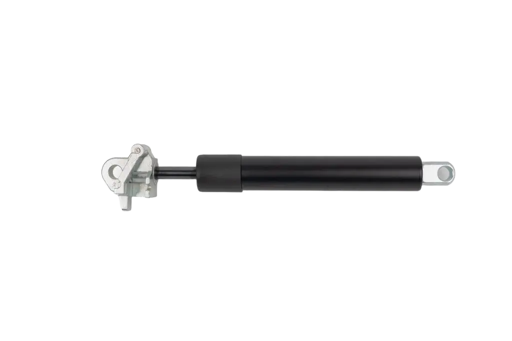
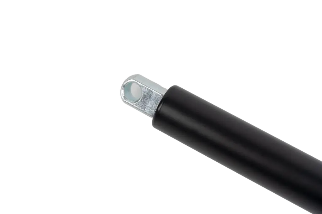
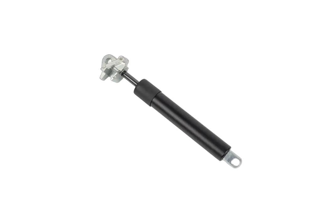
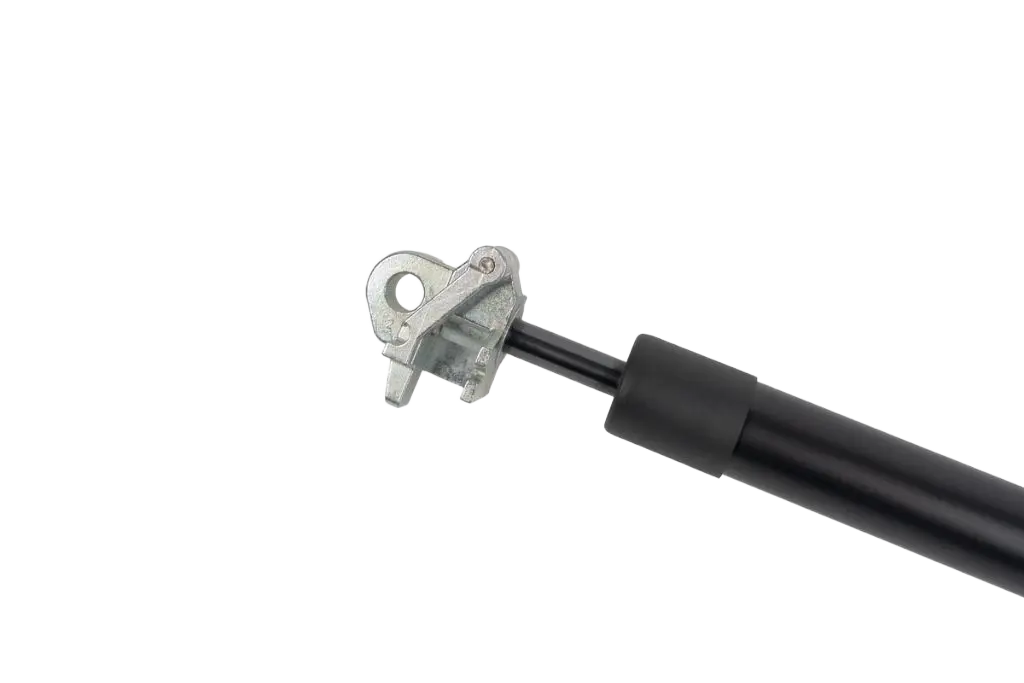
Newton’s rigid locking gas strut uses an oil-filled, semi-rigid design that stays locked when the rod is pulled, giving secure positioning in seats, beds, backrests and adjustable equipment.
- Rigid lock in the extension (pulling) direction with high pull resistance
- Stops and holds firmly at any point along the stroke
- Available in standard and quick-opening semi-rigid configurations
- 8 or 10 mmPiston rod diameter
- 10–500 mmStroke length
- 50–1,250 NForce rating
- 90–650 mmOuter tube length
Overview
A firm hold where the load pulls
A rigid locking gas strut can be stopped and locked anywhere along its stroke. Operate the release and the rod moves freely, helped by the gas force. Let go and the valve closes, holding the rod in place.
This rigid lockable gas spring locks firmly in the extension direction, so pulling on the rod will not move it. Because the internal gas chamber is compact, locking resistance in the compression direction is also relatively high, and the spring rate ratio can be tuned via the internal floating piston position. That is why it is also known as a semi-rigid lockable gas spring or tension locking gas spring. It suits backrests, beds and adjustable workstations where the load pulls on the spring.
It is part of our wider lockable gas spring range, alongside elastic and compression-locking types, so you can match the lock to the way your load acts.
-
Operate the release
Pressing the release pin, directly or via a cable or lever, opens the valve so the spring can move.
-
Adjust freely
Set the position you need. The rod extends or compresses smoothly, assisted by the gas force.
-
Release to lock
Let go and the valve closes. The oil holds the rod rigid against pulling loads.
Key Features
Why choose a rigid locking gas strut
-
Rigid in extension
High resistance to pulling once locked, so the position stays put.
-
Oil-filled lock
Hydraulic oil gives a firmer locked response than a standard elastic locking gas spring.
-
Any position
Infinitely adjustable. Lock at any point along a stroke of up to 500 mm.
-
Built to order
Rod, tube, stroke, force, finish, fittings and release matched to your design.
Specifications
Rigid locking gas strut specifications
Every spring is built to order. Use these ranges as a starting point and we’ll confirm the exact spec.
| Parameter | Range / options | Notes |
|---|---|---|
| Lock type | Semi-rigid | Rigid in the extension direction. Compact gas volume also provides high locking resistance in compression, with spring rate tunable via the floating piston position. |
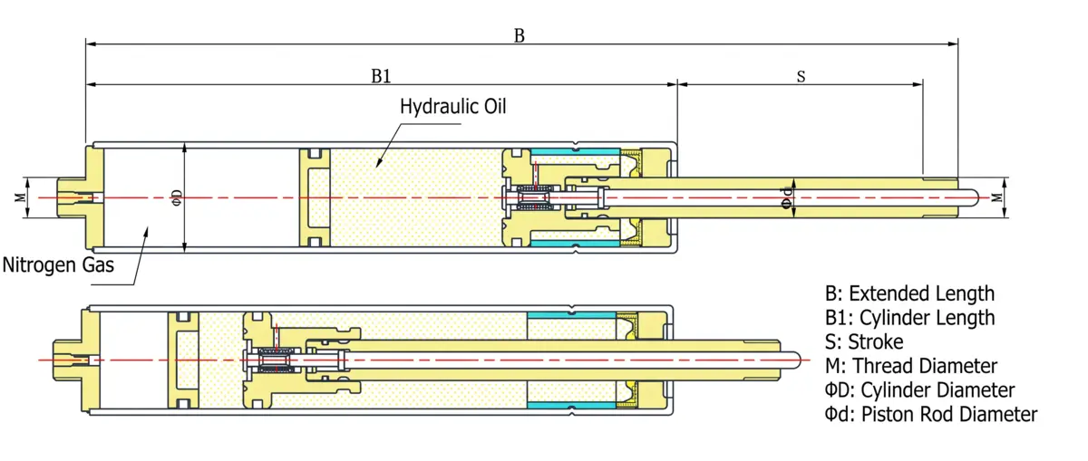
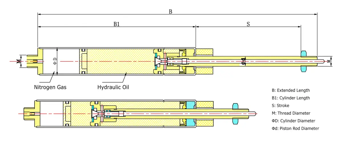
| Versions | Standard or quick-opening | Two semi-rigid designs with distinct valve and end-fitting envelopes (see both schematics below). |
| Fill | Nitrogen gas + hydraulic oil | Gas provides the force; oil provides the firm lock. |
| Piston rod diameter | 8 mm or 10 mm | Larger rods support higher forces and longer strokes. |
| Stroke length (S) | 10–500 mm | Set to the travel your mechanism needs. |
| Outer tube (D × wall) | 22 × 1.0 / 26 × 1.0 / 27 × 1.5 / 28 × 1.5 mm | Selected to suit the rod size and force. |
| Outer tube length (B1) | 90–650 mm | Cylinder body length. |
| Extended length (B) | To order | Overall length with the rod fully extended. |
| Force (F1) | 50–1,250 N | Precisely charged to your required extension force. |
| Finish colours | Black, silver grey, white, chrome, light grey | Durable surface treatments for appearance and corrosion resistance. |
| End fittings | Single-eye, double-ear clevis | Metal for higher strength, plastic for lighter loads. |
| Release | Release pin or cable-release actuator | Operate directly, or remotely via a cable, lever or button in your product. |
Schematics, Force Diagram & Dimension Key
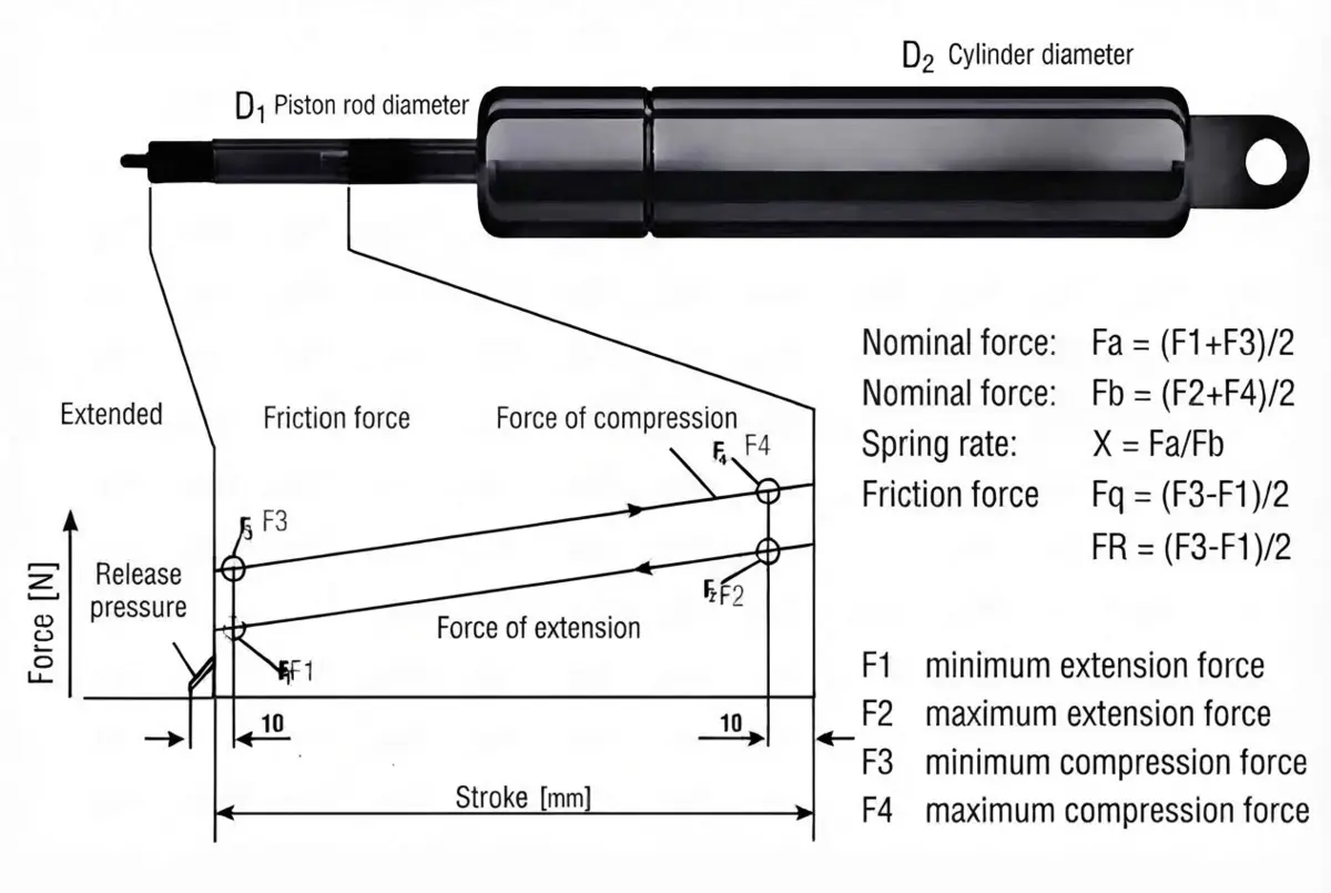
Use the two dimensional schematics and force progression chart below alongside the symbol key when specifying your rigid locking gas strut.
Our tension rigid lockable gas spring series is manufactured in two semi-rigid configurations: the Standard semi-rigid version for everyday multi-position locking, and the Quick-Opening semi-rigid version engineered for rapid valve release and faster reset travel.
Because the internal locking valve and release pin sit inside the threaded piston-rod tip (M), the overall extended length (B), cylinder body length (B1), and mounting geometry vary between single-eyelet and double-ear clevis end configurations shown in Schematic 1 and Schematic 2.
- B
- Extended lengthOverall length, rod fully extended
- B1
- Cylinder body lengthLength of the outer tube
- S
- StrokePiston rod travel distance
- D
- Cylinder diameterOutside diameter of the outer tube
- d
- Rod / hole diameterPiston rod diameter (or eyelet through-hole)
- M
- Mounting threadThread size for end fittings & release pin
- F1
- Extension forceNominal gas force with the rod extended
- F2
- Compressed forceGas force with the rod fully compressed
- FR
- Friction forceDynamic resistance difference between directions
Configuration
Build it your way
Pick the finish, fittings and release that suit your mounting and your product.
-
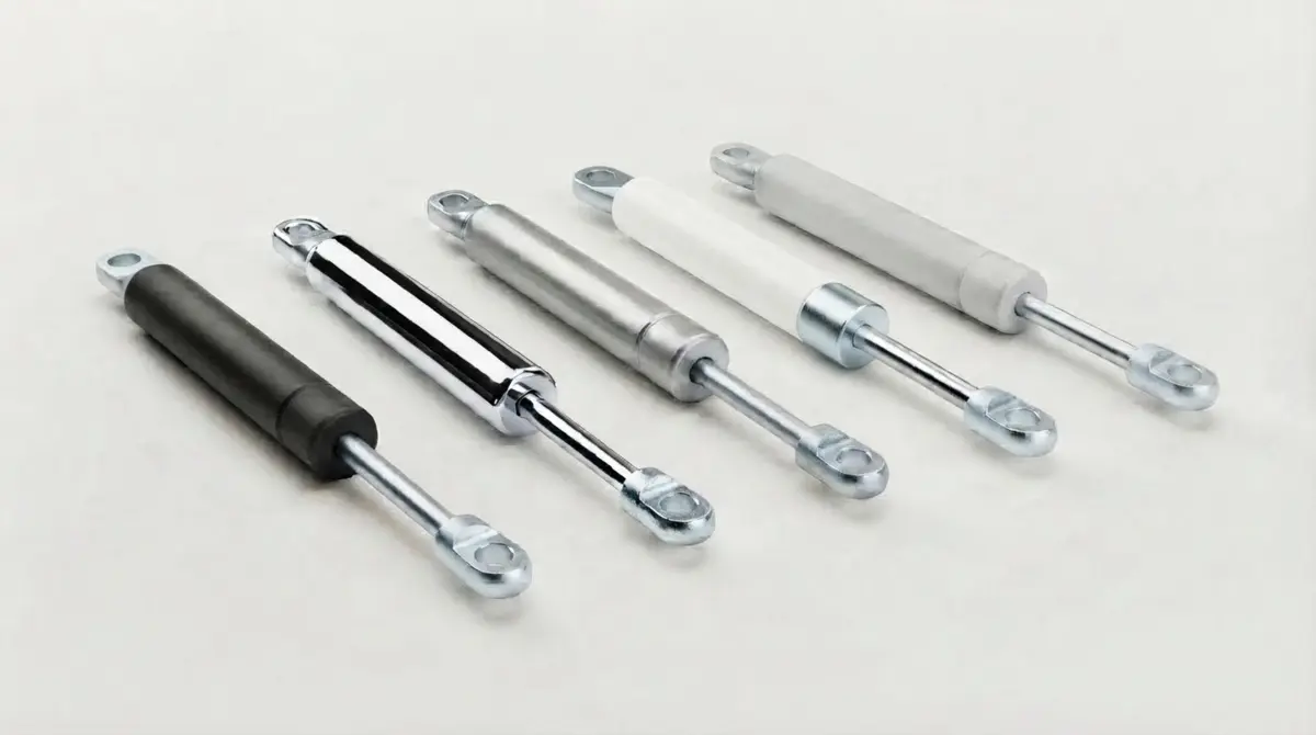
Finish & Colour
Match the spring to your product’s look and environment.
- Black or chrome
- Silver grey or light grey
- White
-
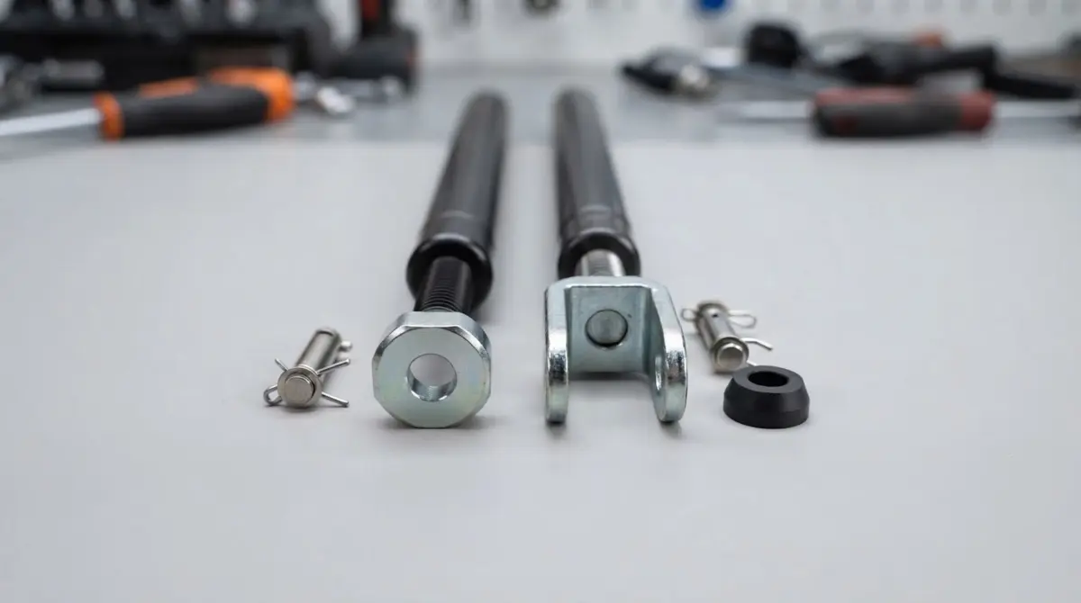
End Fittings
Pivot mounts in metal for strength, or plastic for lighter loads and lower cost.
- Single-eye (eyelet): one through-hole for a pin
- Double-ear clevis: two parallel ears for a sturdier mount
- Custom fittings to your drawing
-
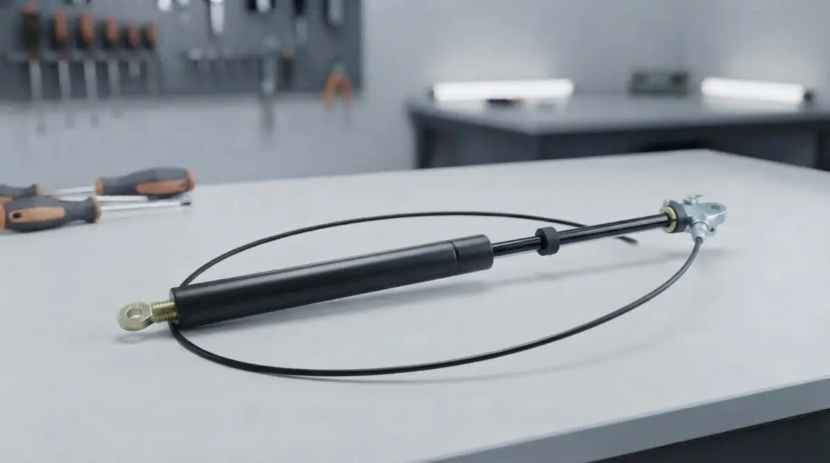
Release Mechanism
Choose how users unlock the spring in your design.
- Release pin, operated directly
- Cable-release actuator for remote operation
- Lever or button via a release cable
What does “semi-rigid” mean?
When locked, a semi-rigid lockable gas spring is rigid in one direction only. This rigid locking gas strut will not move when the rod is pulled, which is why it is also called a tension locking gas spring. Because the internal gas space is compact, locking resistance in compression is also relatively high and the spring rate ratio can be tuned via the floating piston position.
How is this different from an elastic locking gas spring?
An elastic lockable gas spring uses gas only and has some spring-back in both directions. A rigid locking gas strut adds hydraulic oil, which removes that give in extension so positions hold firmly when the load pulls.
Should I choose extension-locking or rigid (compression) locking?
It depends on which way the load acts. If the load tries to pull the rod out, choose this extension-locking gas strut. If it pushes the rod in, such as a table top or work platform pressing down, choose a compression rigid locking gas spring, or the double tube version for a longer stroke from a shorter body. If you don’t need to lock mid-stroke, a standard compression gas spring is the simpler choice.
What is the difference between the standard and quick-opening versions?
Both are semi-rigid, extension-locking designs represented by our two dimensional schematics above. The standard version suits general multi-position adjustment, while the quick-opening version modifies the internal valve and release geometry for rapid unlocking response. Tell us how your product is operated and we’ll recommend the right version.
Can the spring be released remotely?
Yes. A cable-release actuator lets users unlock the spring from a convenient lever or button elsewhere on your product. We’ll confirm cable length and travel for your design.
What do you need to quote a rigid locking gas strut?
Ideally the extended length (B), stroke (S), required force, rod diameter, finish colour, end fittings, release type and quantity. A drawing or photo of the mechanism, showing which way the load acts, helps too.
Get a quote for rigid locking gas struts
Send your stroke, force and mounting details. We’ll recommend the right spec and come back with a clear quote.
Prefer email? info@newtonmatic.com